
Values, then calculate what the result should’ve been.I recently coded an 8-bit counter in Libero and simulated it in ModelSim using Verilog. It is 8 bits, so the application selects 8-bit LFSR with polynomial coefficients taken from the table in 1. clk(clk) ) but I do not remember if that if Verilog or an added feature in. / 16 bit counter / module counter (clk, reset, count) input clk, reset output 14:0 count reg 14:0 count always. ready(ready) ) I believe you can abbreviate matching name and size to just. In this case, weĬan (now) use the C multiplication operator. wire 7:0 databyte 'X' wire startsend (count 100000000) uartsend sender(. Multiplying two numbers together and compare the results. if ( OPT_SIGNED ) sout = sbits ( m_slow -> o_p, NA + NB ) else sout = ubits ( m_slow -> o_p, NA + NB ) ĭid we get the right answer? For this, we’ll use a second method of

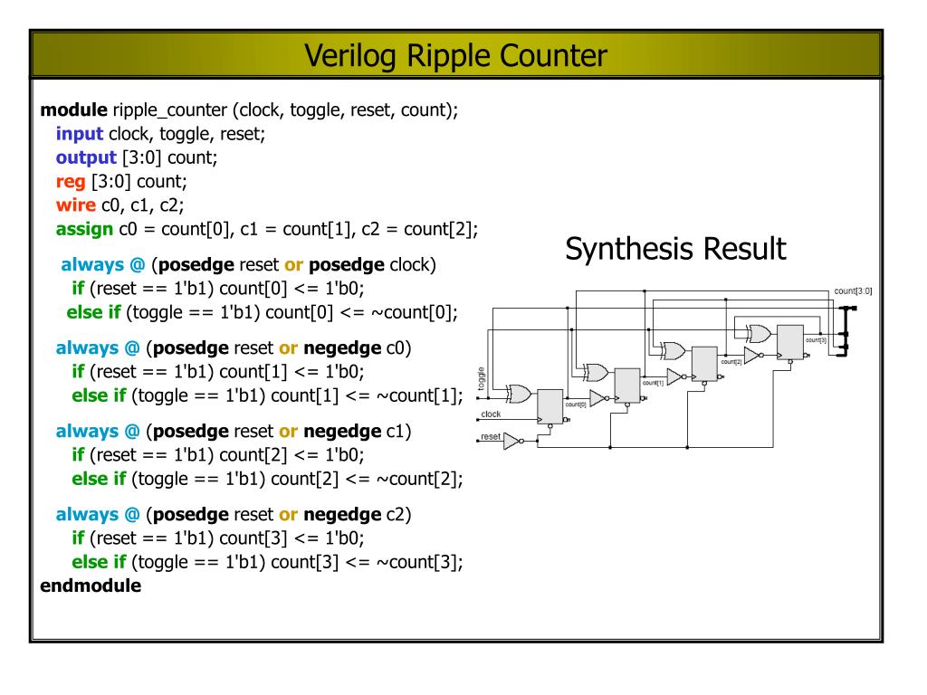
The next step is to verify that we received the right answer. In C++ code, this multiply might look like: unsigned multiply ( unsigned a, unsigned b ) If this still sounds confusing, let me try explaining this idea one more time. Result accumulator any time the respective bit in b was a 1. The top design block consists of four T-Flip Flop. We’ve taken a,Īnd shifted it to the left one bit (digit) at a time, and added it to our To proceed with Verilog Code, we shall first understand the structure of the 4-bit Ripple Counter. This is a basic “shift-and-add” multiplication algorithm. Row number and m is the position within the row, have been generated theyĪre all then added together to yield a result. Once all the partial product rows, that is the pnm rows, where n is the Now looking at binary digits instead of decimal ones. You are already familiar with, with the only difference being that we’re (s) Y S1 else Y S2 S2:if (z 0) Y S2 else Y S3 S3:if (s) Y S3 else Y S1.
Verilog bit count code#
Same way, only it gets shifted over one more column and so forth.Īgain, this should look very much like the long-multiplication algorithm Verilog code for the bit-counting circuit (Part a). P1* row is shifted left from the p0* row. The six p1* digits represent multiplication of a by b1. If b0 is 1, p0* will be equal to a otherwise zero. In this figure, the six p0* digits represent the multiplication ofĪ by b0. Simple as always ( posedge i_clk ) if ( ce ) result Also, it starts counting down from the next clock from whatever value it. We have two inputs i.e., clock and reset and q is output. It counts up when you set the countupdown bit as 1b and runs down when it is 0b.

The basic idea in an asynchronous n-bit ripple up counter is to have one toggle flip-flop for each of the n bits. Let us consider the overall outside structure of Ripple Counter. Answer: Since this sounds like a homework problem I’ll give an explanation first try to implement it yourself first if you can. For time being ignore the input and output of T-Flip Flop. For these FPGAs, performing a multiply is as To proceed with Verilog Code, we shall first understand the structure of the 4-bit Ripple Counter. The good news? Several FPGAs, such as many of the Xilinx and Intel FPGAs, allĬontain a limited number of multiply units, often called DSPs for short, Here’s the bad news: Multiplies are hard to do in hardware. Want to build your own CPU? If you build anything more than a basic CPU, All of these FPGA algorithms require multiplies.

Processing algorithms require multiplies:Ĭontrol systems, and more. Indeed, I might argue that all of the good signal Mathematical algorithms, such as my favorite DSP filtering algorithms, all Purpose, number crunching is certainly one of the basic ones. If you are author or own the copyright of this book, please report to us by using this DMCA report form. This document was uploaded by user and they confirmed that they have the permission to share it.
Verilog bit count download#
You know, those serious number crunching applications. Download Verilog Code For 4 Bit Ring Counter With Testbench. One of the basic purposes of FPGAs is to run algorithms, and to run them fast.


 0 kommentar(er)
